The Wide Field Survey Telescope (WFST) is a 2.5m optical telescope with primary-focus optics designed for a wide 3$^{\circ}$ field of view. A 3-D sketch of the telescope structure is shown in Figure 1, where telescope tube consists of a square center hub, the lower and upper Serrurier trusses, the primary focus ring, four spider plates, and the primary-focus assembling tube. The lower and upper Serrurier trusses are connected with the lower and upper surfaces of the central hub, respectively. The primary focus ring sits on the top of the upper Serrurier truss and provides support for the primary-focus assembling tube through the triangle spider plates.
A mosaic CCD camera, a set of corrector lenses, a filter exchanging mechanism and a field de-rotation and re-focusing mechanism are integrated into a unit known as a primary-focus assembly (PFA). The PFA is attached to the primary-focus assembling tube via a hexapod mechanism that leads to fine alignment of the PFA relative to the primary mirror.
The primary mirror is located at the other end of the telescope tube, which is assembled on an alt-azimuth mount. Ball-bearings are utilized on both the elevation and azimuth axes, and the rotation is driven by direct drive torque motors for high stiffness and precision. An auto-guiding system based on focal-plane guide sensors is employed to conduct closed-loop tracking during operation.
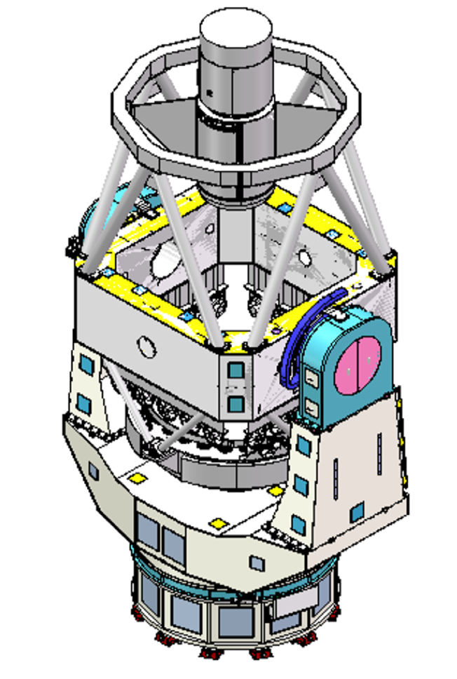
Left panel: Figure 1, 3D model of the telescope structure.
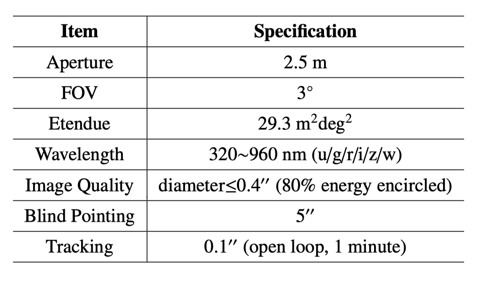
Right panel: Table 1, Top-level specifications for WFST.
The top-level telescope specifications are listed in Table 1. The optical layout of WFST is shown in Figure 2. The optical system consists of a primary mirror, five corrector lenses, an atmospheric dispersion compensator (ADC), and the filters of six optical bands. The primary mirror (M1) is a thin meniscus made of Zerodur with a diameter of 2.5m and a thickness of 120 mm. It is an F/2 hyperbolic concave mirror with high-order aspheric terms. The first corrector lens, 970mm in diameter, is the largest one. The second corrector lens is a negative lens with a concave aspheric back surface. The third and fourth lenses are both spherical. To control the chromatic aberration, the third lens is made of Schott’s N-BK7 glass. The fifth lens also serves as the window for the detector dewar. The concave front surface of this lens is another aspheric surface. The final focal plane is a flat surface with a platescale of 0.03 mm/arcsec. To balance image quality and system transmission (especially in u-band), a lensm ADC design is adopted. The ADC consists of a pair of lensm (lens with wedge) that rotate in opposite directions to compensate atmospheric dispersion. This design avoids the use of flint glasses and therefore increases the UV transmission. Raytracing simulations show that 80% of the spot energy is encircled within a diameter of 0.4$^{\prime\prime}$ across the full 3$^{\circ}$ FoV in such a primary-focus optical design.

Figure 2: Optical layout of WFST.
The primary mirror is supported by 54 axial supports and 12 lateral supports. Under the gravitational load, these supports coordinate to deliver an r.m.s. surface error of 3.7 nm for a zenith pointing and 4.2 nm for a horizontal pointing. Both axial and lateral supports are given by pneumatic actuators based on diaphragm cylinders. Their output forces are measured by a load cell, which acts as the feedback into a precision control loop. Similarly, four additional lateral positioners adjust and fix the mirror position in the lateral directions.
As the core of our primary-focus design, the PFA is an integrated unit that accommodates five corrector lenses, a pair of ADC lenses, six filters, a shutter and a mosaic CCD camera. The corrector lenses are supported by invar lens cells, which are connected to the invar pads glued to the rim of the lenses via flexures. The lens cell is then mounted to the inner shell of the PFA through spacers and adjusting pins that adjust the tip/tilt and the decenter of each lens. A total of 24 lateral supports are used for C1, while other lenses use 12 supports per each. A filter exchanging mechanism moves the filter at work into the working position, while keeping the other five filters in stow positions around the cryostat of the camera. The overall PFA structure extends a total length exceeding 2.7 meters and a total weight of 1.8 tons approximately.
A look-up table (LUT) based on finite element analysis is firstly established to carry out the correction process, where both rigid-body misalignment errors of the PFA and surface figure errors on M1 due to gravitational deformation at various elevation angles as well as large-scale thermal deformation as a result of ambient temperature variation are corrected. Furthermore, close-loop active wavefront corrections based on focal-plane wavefront sensors are used to correct the residual errors in the PFA alignment and the low-order bending errors on M1.
Active optics (AO) is equipped to keep the telescope in a seeing-limited condition and to reduce PFA misalignment and primary mirror deformation. In this AO system, we utilize the curvature wavefront sensors at each of the four sides of the 3$^{\circ}$ field to measure the overall wavefront aberrations in real time. Each of these wavefront sensors is made up of two separate CCD detectors delivering intra- and extra-focal images, respectively. The measured defocused images are decomposed into Zernike polynomials, and their deviations from the designed values are used as merit functions. An iterative damped least square (DLS) method then minimizes the merit functions until an acceptable level is reached. In each correction period, the output wavefront corrections, interpreted as the 5-DOF rigid-body motions for PFA and lower-order Zernike correction coefficients for M1, are sent to the telescope control system, which drives the PFA hexapod and M1 active supporting system accordingly.